2025 AIChE Annual Meeting
(691b) Process Design and Comparison of Three Innovative Technologies for Biomethane Production and/or Purification and Upgrading from Biomass and Biological Wastes
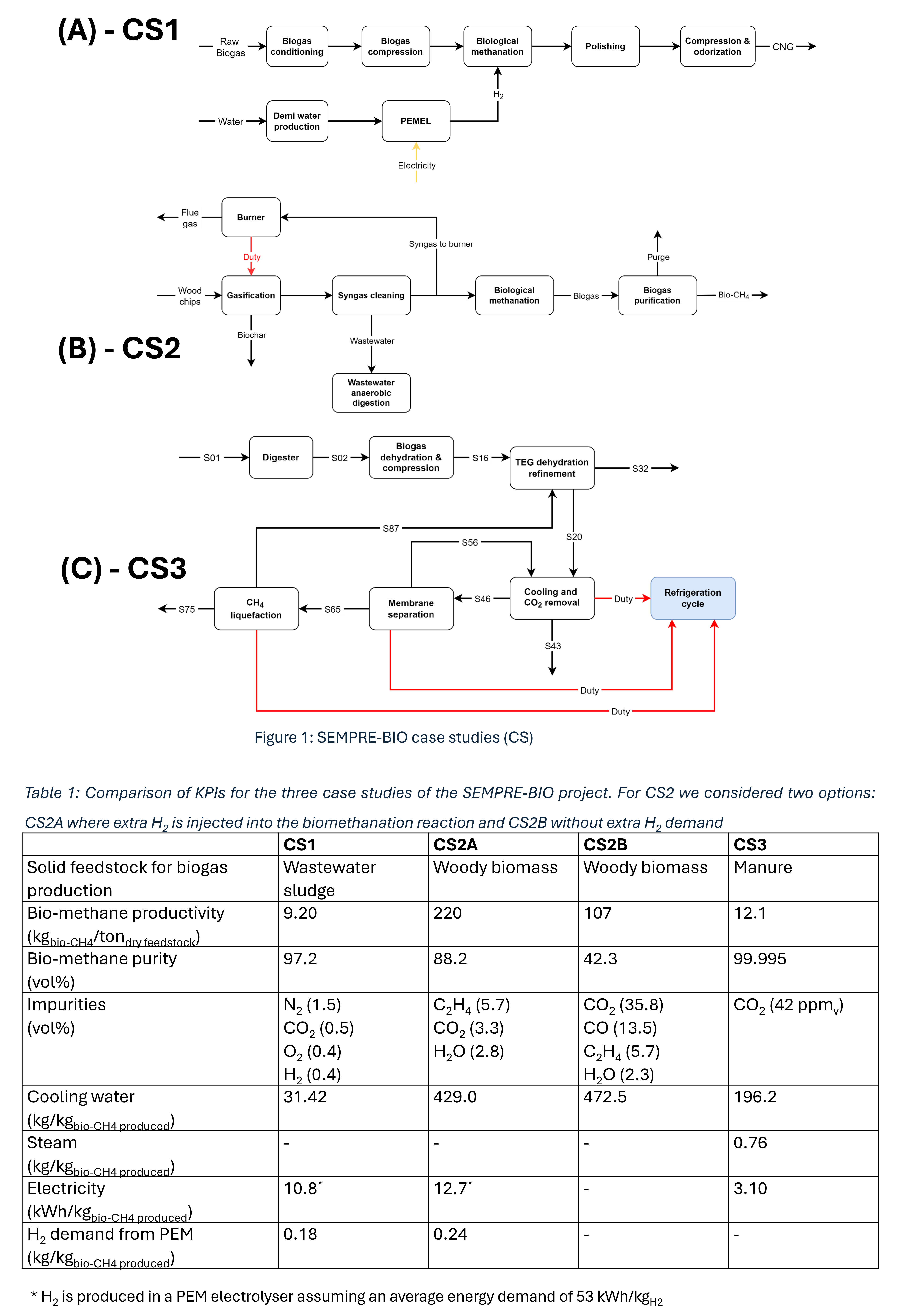
The EU-funded project SEMPRE-BIO operates within this framework. The project considers three different technologies, reported here as case studies (CSs), for producing and upgrading bio-CH4 from several biological wastes. All the mentioned technologies are piloted and validated through the project. The three technologies are briefly described here.
CS1 (Figure 1A) turns raw biogas from the anaerobic digestion of wastewater treatment sludge into synthetic compressed natural gas (CNG). The wastewater treatment plant (WWTP) is located in Catalonia and the treated sludge volume is retrievable on the official webpage (Baix Llobregat WWTP | ACCIONA). The biogas yield of the sludge digestion is 14.8 Nm3biogas/m3sludge based on experimental evidence [1]. Biogas from anaerobic sludge digestion is purified before compression. The compressed biogas is conveyed to a biological biomethane reactor where biogas is co-fed with green H2 from a PEM electrolyser. The reactor works at (~55°C) and under pressure (4-9 bar abs) to improve the solubility of hydrogen inside the aqueous phase, where thermophilic bacteria catalyses biomethane production, as well as the reverse water-gas shift (RWGS) reaction. The gas mixture leaves the reactor and passes through a polishing step and compression to 20 MPa refine the biomethane quality and final delivery conditions as compressed natural gas (CNG).
Hardwood chips are the feedstock for CS2 (Figure 1B). The wet biomass is gasified using the moisture to generate the steam for the gasification. The heat for the endothermic thermochemical process is supplied from the combustion of a fraction of the produced syngas. After the first purification stage and split of the part to be burnt, the remaining syngas is conveyed to a biological methanation reactor, and the resulting gas is fed to a purification stage, e.g., membrane to refine the concentration of bio-methane suitable for transport applications.
CS3 (Figure 1C) proposes an innovative electrified solution for the separation of biomethane from biogas and successive purification. The biogas is generated within a digestor starting from farm manure. The yield of anaerobic digestion of manure is 33 L/kgmanure, i.e., 37 kgbiogas/tonmanure [2]. Biogas is purified from ammonia and hydrogen sulphide traces, dehydrated, and compressed (S16). The residue moisture is reduced below 5 ppmv (S20) through a TEG dehydration process since the downstream separation and purification are run at cryogenic conditions and water solidification is undesired. The resulting dry biogas is cooled down and CO2 is removed in a distillation column. The CO2 is recovered as a liquid stream purity is >99.99% suitable for food applications. The resulting biomethane-enrich gas stream (S46) undergoes further purification through a membrane to purge the residue CO2 and deliver almost pure biomethane (S65) which is liquefied (S75) thanks to an open-loop Brayton cycle where the gas boil off tends to accumulate the residue traces of CO2. Therefore, the stream is recycled back to the TEG dehydration step. The separation of bio-CH4/biogenic CO2 occurs in the cold box of the process. A conventional refrigeration loop with an ethane-propane mixture keeps cryogenic conditions within the cold box. The Joule-Thompson effect is here exploited to generate the frigories.
All the described technologies are piloted within the project. Process flowsheets have been developed and the corresponding energy and material balances solved in COFE V3.7, a CAPE-open license-free process simulation software, released by AmsterChem (AmsterCHEM - Mission). The assumptions for the flowsheet development are disclosed in [3].
The present contribution aims at:
- Presenting the modelling and process design of the three technologies starting from the same feedstock input to (i) identify the most suitable options for the modelling of this kind of application and (ii) scale-up strategies.
- Identify and compare the most relevant key performance indicators (KPIs) such as
- The specific biomethane production per unit of biomass/waste.
- The utility/consumable consumption per unit of produced biomethane. Steam and any other chemical consumed within the process is accounted for.
- Electricity demand per unit of mass of biomethane.
- Additional KPIs specific to the case study
Table 1 gathers the results:
- CS3 is tailored to purify the bio-CH4 from the biogas. Hence, no reactive steps to increase bio-CH4 content from biogenic COx are implemented. For other case studies the purity of delivered bio-CH4 is lower since the upstream reactors and the associated chemistry generates several volatile impurities and the purification is challenging. Remarkably, for CS2, the injection of extra H2 in the biological methanation increases the biomethane productivity corresponding to a higher conversion of COx. Anyway, further purification stages should be accounted for in future to deliver a bio-CH4 whose purity is comparable to CS3.
- The specific electricity demand is higher for CS1 and CS2A because of the electricity demand to run PEM electrolysers to supply the H2 for biomethanation reactors. PEM demand is 96% of the total electricity consumption; while the remaining 4% is for bio-CH4 compression to the delivery pressure, i.e., 20 MPa. For CS2A this item represents almost the totality of the electricity demand. In CS3 the electricity demand is mainly associated with the refrigeration block to keep the temperature in the cold box (55.2% of the total electricity demand) and the open Brayton loop for the liquefaction of methane (22.1%).
- CS3 is the only process where steam is consumed. Steam is needed in the reboiler of the distillation column for TEG regeneration. TEG (tri-ethylene glycol) is used as entrained for deep moisture removal before the cold box of the process to avoid its solidification within downstream units operated at deep cryogenic conditions.
Acknowledgement
The present work received financial support from the Horizon Europe program through the SEMPRE-BIO project (Grant Agreement N. 101084297).
References
[1] A. Masłoń, An Analysis of Sewage Sludge and Biogas Production at the Zamość WWTP, in: Z. Blikharskyy, P. Koszelnik, P. Mesaros (Eds.), Proceedings of CEE 2019, Springer International Publishing, Cham, 2020: pp. 291–298.
[2] K. Kusmiyati, D.K. Wijaya, B.J.R. Hartono, G.F. Shidik, A. Fudholi, Harnessing the power of cow dung: Exploring the environmental, energy, and economic potential of biogas production in Indonesia, Results in Engineering 20 (2023) 101431. https://doi.org/10.1016/j.rineng.2023.101431.
[3] M. Gilardi, F. Bisotti, B. Wittgens, Modelling of Bio-Methanation, a Promising Route for GHG Emission Reduction, in: Proceedings of the 17th Greenhouse Gas Control Technologies Conference (GHGT-17) 20-24 October 2024, Social Science Research Network, Rochester, NY, 2024. https://doi.org/10.2139/ssrn.5016466.