2025 AIChE Annual Meeting
(289c) Jet Mixing in Tall Tanks with Non-Optimum Jet Geometries
Authors
Uθ / D = K1 (Z / D)2
Or:
K1 = U θ D / Z2
There are cases where the jet path might not be optimized and impinge on the vessel wall below the surface. For example, if a vessel has an optimized jet but must occasionally operate with the liquid surface above the optimum impingement point, with the larger volume, to allow for upset conditions downstream. The FMP consortium also measured blend times in vessels where H / T ≤ 4 [4] and under these conditions found that the blend times increased and that the flow patterns became more complex.
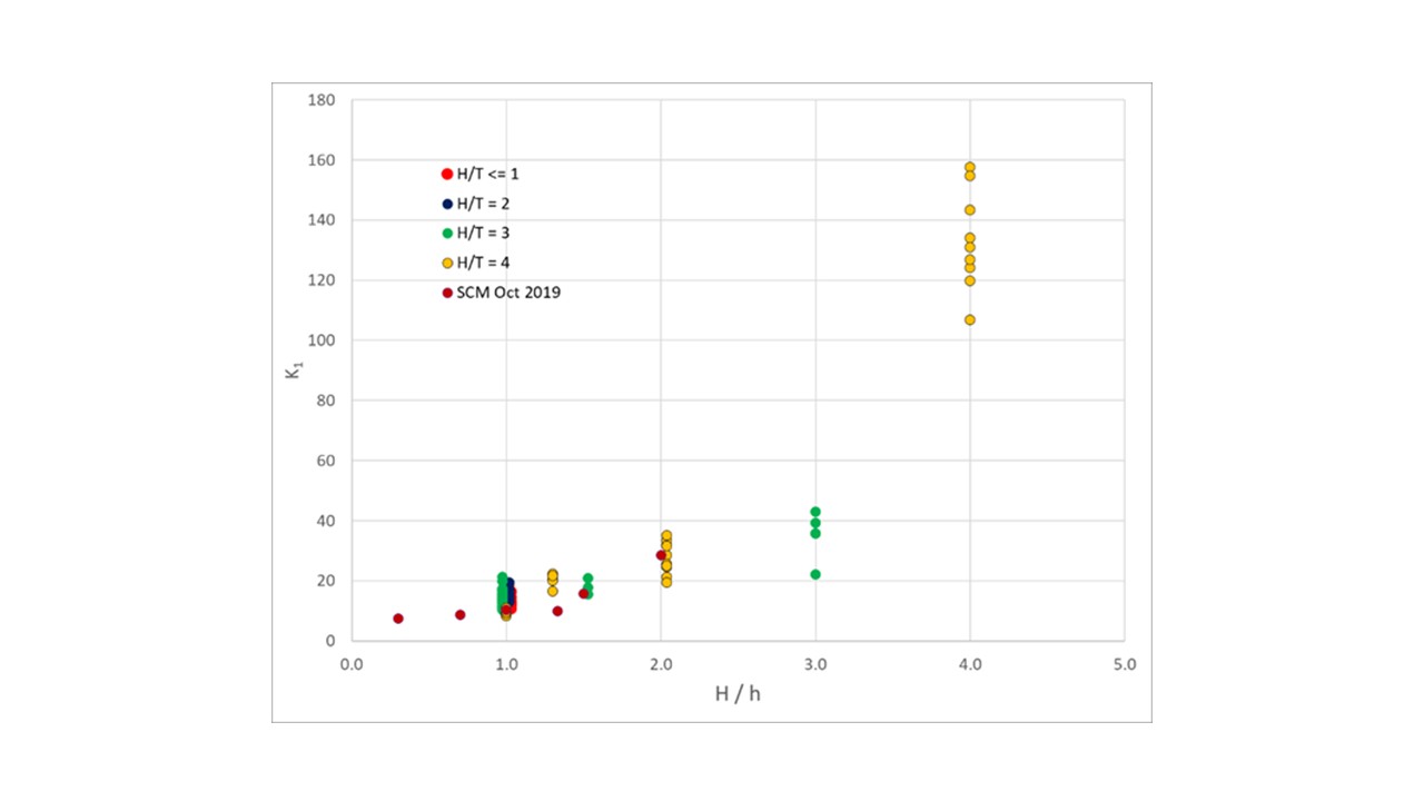
These data have been reanalyzed and the results are presented here. The constant becomes a function of the ratio of the liquid depth to the height of the impingement point above the base:
K1 = K2 (H / h)
If the jet impinges at the optimum point, H / h = 1 and K1 = K2. This relationship holds for H / T ≤ 3 but fails for data measured at H / T = 4. For the tallest case the constant K2 is 34.7 indicating that the blend time is approximately 10 times longer, for a given power input, than a vessel where H / T ≤ 3. The data are plotted in Figure 1.
Pendall [4] reported a change in flow patterns when H / T = 4 with the liquid dividing into two regions. A computational fluid dynamics model has been developed using lattice-Boltzmann large-eddy simulation to investigate the flow patterns across the range of H/T ratios studied experimentally an generate further insights into the mixing phenomena in these vessels.
The model will also test whether the model can capture the physics of a free, round jet such as the dimensions of the potential core, the decay of the center-line velocity along its path length and the distribution of velocities across the jet’s diameter.
Nomenclature
D is the jet nozzle diameter
H is the liquid depth
h is the height above the base where the jet impinges on the opposite wall from the nozzle
K1, K2 are constants
T is the vessel diameter
U is the jet velocity at the nozzle
Z is the jet’s free path length (= (T2 + H2)1/2)
θ is the blend time
References
- Grenville, R. K. & J. N. Tilton, “A new theory improves the correlation of blend time data from turbulent jet mixed vessels”, Eng. Res. Des., vol. 74, no. A3, pp. 390 - 396, 1996
- Grenville, R. K. & J. N. Tilton, “Turbulence or flow as a predictor of blend time in turbulent jet mixed vessels”, In of the 9th European Conference on Mixing, Paris, France, 1997
- Grenville, R. K. & J. N. Tilton, “Jet mixing in tall tanks: comparison of methods for predicting blend times”, Eng. Res. Des., vol. 89, no. 12, 2501 – 2506, 2011
- Pendall, N. H., “Mixing Time Measurements in Tall Jet Mixed Vessels”, FMP Interim Report 1026, October 1987
- Rajaratnam, N., “Turbulent Jets”, ch. 2, Elsevier Scientific Publishing Company, Amsterdam NL, 1976