2025 AIChE Annual Meeting
(586o) Hydrodynamic Analysis of High Viscous Oil-Water Flow Upstream and Downstream of a CAF-Inducing Device
Authors
Due to the decline of light crude and depleting onshore oil fields, the demand for heavy crude has increased rapidly. Heavy crude is defined as petroleum that has an API gravity in the range of 10-22 degrees. These oils are characterized by high density, high viscosity, and low mobility, which greatly impact their extraction and transportation process. Thus, flow assurance is a challenge [1]. Various methods, such as heating and dilution, have been used to facilitate transportation, but these methods are cost-intensive. One promising alternative is the water lubricated transport of high viscous oil by core annular flow (CAF) configuration. In this technique, water is pumped along with the high viscous oil in such a way that it forms a thin annular film around it. This reduces frictional pressure drop considerably. The reduction is to such an extent that the two-phase pressure drop becomes almost equal to the one observed for the single-phase flow of water only. Despite being energy-efficient, CAF has not been widely implemented in industries. Stabilizing CAF over long distances and in particular re-establishing it after pipe fittings are its limitations. Past studies have reported that upon encountering these fittings, CAF gets disrupted and leads to pipe wall fouling by oil. This causes pipe blockage and a high pressure gradient. However, one study by the authors [2] have found that when a pipe experiences a sudden expansion, CAF forms regardless of the upstream flow pattern. Identical observations have also been reported by Dehkordi et al., [3].
Based on this, the authors have proposed a unique device (Indian Patent no: 5447/ASA/PP-4221/IIT, Kgp (AN)) that can be used to establish CAF and re-establish it over a wide range of oil and water flow rates and tested it using lubricating oil and tap water. The device referred to as “CAF-Inducing device” comprises of an abrupt axisymmetric expansion of ratio 1:2 followed by a gradual tapering (5º taper angle) section to restore the pipe to its original dimension. The performance of the device is evaluated in terms of pressure gradient reduction and minimum water cut required to establish CAF. In this study, we analyze the experimental data on pressure drop under different flow conditions and rationalize the trends from in-situ holdup measurement using a simplified two-fluid analysis.
Experimentation
Experiments are performed by installing the device in the center of a horizontal 25mm diameter and 4 m long perspex (transparent) pipe. The range of oil (Qo) and water flowrates (Qw) are varied from 3LPM to 30LPM and 10LPM to 1LPM respectively. The pressure drop is measured in both upstream and downstream sections using Honeywell Differential Pressure Transducer (Model: STD 725) and the flow patterns are noted using a high-speed camera (Nikon, model Micro LC320S). To rationalize the pressure gradient data, the in-situ oil holdup is measured by the quick closing valve technique [4] where a pair of solenoid valves placed 1m apart in the fully developed flow region, are closed instantaneously to trap the flowing mixture. The mixture is then drained to a measuring cylinder and the volume of oil collected is estimated after gravity separation. Air pumped in from an air nozzle at the top of this pipe section ensures complete drainage of the liquids to the measuring cylinder.
Results and Discussion
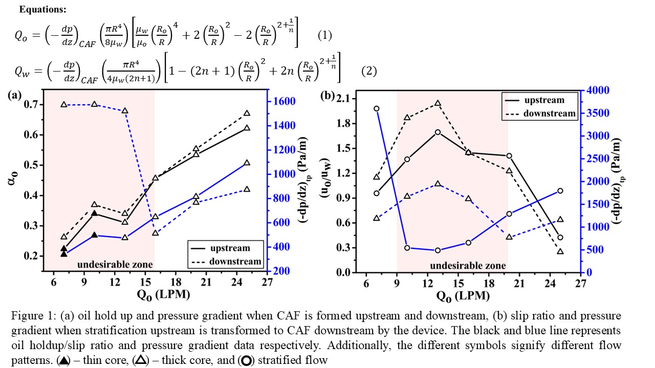
Fig. 1 presents the results of oil holdup fraction (αo) and pressure gradient (-dp/dz)tp data for different oil flowrates. The flow patterns, superimposed in the figure, shows the existence of CAF downstream of device when the upstream flow pattern in either stratified of CAF. Further, the CAF upstream of device, is mostly characterized by a thin core flow (dcore/D < 0.65) while downstream of device, the flow pattern is predominantly thick core surrounded by a thin water film. For a better understanding, the results are presented under two conditions: (i) when CAF is formed in both upstream and downstream sections, and (ii) when stratified flow upstream is transformed by the device to CAF downstream.
(i) With CAF in both upstream and downstream sections
In this case, Fig. 1a shows that although CAF forms both upstream and downstream of device, the pressure gradients are different under the same oil and water flow rates. The pressure gradient is lower in the downstream compared to the upstream section for Qo>16 LPM. This suggests that the device is energy efficient at higher oil flowrates. The lower pressure drop in the upstream section for Qo<16 LPM (shown by red color in Fig 1a), arises because the water annulus in the downstream section becomes turbulent as defined by the in-situ Reynold’s number (Re>5000), while in the upstream section, the water film in most cases is in transition regime. The opposite is observed beyond 16LPM oil flow. This has been further corroborated by a two-fluid analysis of the CAF.
Eq. (1) and (2) relates pressure gradient (-dp/dz)CAF, phase flow rates (Qo,Qw), core radius (Ro), fluid properties (μo,μw) and the parameter n that depends on Reynold’s number. The equations are derived for laminar flow of the oil core and the flow of water that can be either laminar or turbulent depending on the in-situ Reynold’s number of the annulus. Qo,Qw and (-dp/dz)CAF are known along with fluid properties and conduit radius. Simultaneous solution of the non-linear equations (Eq. (1) & (2)) gives the value of and n. The calculation is same for the upstream and downstream sections. Interestingly, oil holdup is consistently higher in the downstream section.
(ii) With stratified flow upstream and the device transforms it to CAF downstream
The trend of pressure gradient data in this case can better be explained from the slip ratio defined as (uo/uw). The results show that a higher (uo/uw), corresponding to a high interfacial shear leads to a higher pressure gradient (Fig. 1b). The data also reveals that stratification upstream can result in a higher αo. This is primarily due to pipe wall fouling by oil.
Conclusion
- The device is energy-efficient (low pressure gradient downstream of the device compared to upstream) for Qo>16 LPM, corresponding to an inlet water fraction, β<0.4, when CAF forms both upstream and downstream, but thick core predominates in the downstream section.
- When the device transforms upstream stratified flow to CAF downstream, the device leads to energy-efficient transportation by lowering downstream pressure gradient for β<0.15.
- When stratification upstream leads to CAF downstream, higher oil holdup in the upstream section at some oil flowrates is due to oil accumulation caused by pipe wall fouling.
References
[1] R. Martínez-Palou et al., “Transportation of heavy and extra-heavy crude oil by pipeline: A review,” J. Pet. Sci. Eng., vol. 75, no. 3–4, pp. 274–282, 2011, doi: 10.1016/j.petrol.2010.11.020.
[2] T. Balakhrisna, S. Ghosh, G. Das, and P. K. Das, “Oil-water flows through sudden contraction and expansion in a horizontal pipe - Phase distribution and pressure drop,” Int. J. Multiph. Flow, vol. 36, no. 1, pp. 13–24, 2010, doi: 10.1016/j.ijmultiphaseflow.2009.08.007.
[3] P. Babakhani Dehkordi, L. P. M. Colombo, E. Mohammadian, A. Azdarpour, and G. Sotgia, “The influence of abruptly variable cross-section on oil core eccentricity and flow characteristics during viscous oil-water horizontal flow,” Exp. Therm. Fluid Sci., vol. 105, no. April, pp. 261–277, 2019, doi: 10.1016/j.expthermflusci.2019.03.026.
[4] J. Shi, L. Lao, and H. Yeung, “Water-lubricated transport of high-viscosity oil in horizontal pipes: The water holdup and pressure gradient,” Int. J. Multiph. Flow, vol. 96, pp. 70–85, 2017, doi: 10.1016/j.ijmultiphaseflow.2017.07.005.