2025 AIChE Annual Meeting
(474f) Heat Transfer, Power Consumption, and Scale-up in the Agitation of Newtonian and Non-Newtonian Fluids in Stirred Tanks with Spiral Coils
Among these surfaces, jackets are the most commonly used due to their ease of fabrication and cleaning. However, jackets are limited in their heat transfer capabilities because they only affect the tank wall, making them unsuitable for large-diameter tanks. An alternative is the use of helical coils installed within the tank, which provide direct contact with the process fluid and thus offer improved thermal efficiency. The drawback of helical coils, however, lies in their cleaning difficulty. Spiral coils, often located at the bottom of the tank, are compact versions of helical coils. Conceptually, spiral coils share the same limitation as jackets in that they occupy only a portion of the tank's surface area. Nevertheless, when used with axial impellers, which direct the flow toward the tank bottom, spiral coils can achieve thermal performance comparable to that of helical coils. Additionally, spiral coils are easier to clean than helical configurations.
Regardless of the chosen surface, baffles are necessary to break vortices during agitation. Vertical tubular baffles serve a dual purpose as both vortex suppressors and heat exchange surfaces. Independent of the surface type used, the determination of U depends on internal and external convective heat transfer coefficients, where the external coefficient—associated with the agitated fluid—is the most complex to evaluate.
Current literature presents limited information on the thermal design of tanks with jackets, helical coils, spiral coils, and vertical tubular baffles when handling non-Newtonian fluids. In this context, the present study aims to analyze heat transfer, power consumption, and scale-up in mechanically agitated tanks equipped with spiral coils and operating with Newtonian and non-Newtonian fluids. Additionally, the study proposes scale-up methodologies for agitated tanks operating with non-Newtonian fluids that follow the power-law rheological model.
The experimental setup consisted of two acrylic tanks, with working volumes of 10 and 50 liters, each fitted with an internal spiral coil. Two types of impellers were tested: a four-blade axial impeller with blades inclined at 45°, and a six-blade flat radial turbine. Distilled water was used as the hot fluid, flowing through the internal spiral coil. The cold fluids, placed in the tank and agitated, included aqueous solutions of carboxymethylcellulose (CMC) at 0.5%, 1.0%, and 1.5% mass concentrations; an aqueous solution of Carbopol 940 at 1.5%; aqueous sucrose solutions at 20% and 50%; and distilled water. The rheological properties of the non-Newtonian fluids (CMC and Carbopol) were characterized using a Brookfield DV-III rheometer across a temperature range of 25°C to 50°C.
Initial tests were carried out in the 10-liter tank. Each fluid was subjected to agitation and heating using rotational speeds ranging from 200 to 1100 rpm. The temperature increase during each test ranged from 15°C to 20°C, depending on the impeller. In the 50-liter tank, the rotational speed ranged from 100 to 1000 rpm, maintaining the same target temperature increases. The temperature of the cold fluid was measured at three distinct vertical positions: near the bottom, at mid-level, and near the surface, using thermocouples positioned accordingly. Readings were taken every minute.
The hot fluid entered the coil at a constant temperature of 65°C, with a fixed flow rate of 1.0 L/min for the 10-liter tank and 1.5 L/min for the 50-liter tank. Inlet and outlet temperatures were recorded to ensure consistency and to evaluate the heat transferred to the cold fluid. All experiments were performed in batch mode, and temperatures from five thermocouples were recorded at one-minute intervals until the desired thermal variation was reached.
Mechanical power consumption was estimated based on torque calculations. Torque was determined by measuring force using a dynamometer mounted on a balancing arm connected to the motor. For the 10-liter tank, three arm lengths were used: 122 mm, 241 mm, and 404 mm. For the 50-liter tank, the lengths were 200 mm, 400 mm, and 600 mm. Three measurements were taken per test to compute the arithmetic mean and thus obtain a more reliable power value. This approach also helped to detect any measurement fluctuations. All force readings were taken at the initial temperature of the experiment, ensuring that power consumption was evaluated under the most demanding conditions—when fluid viscosity is highest. Note that power consumption tests were not conducted for Newtonian fluids (distilled water and 50% sucrose solution), as well-established predictive models exist in the literature for these cases.
Using the experimental data, empirical scale-up correlations were derived between the two tank sizes. These correlations accounted for impeller type and heat transfer surface while maintaining geometric similarity. Three scale-up criteria were considered: constant tip speed, constant convective coefficient, and constant power consumption. These relations allowed for the prediction of thermal and mechanical behavior at larger scales.
The results were divided into three main groups. The first involved evaluating heat transfer parameters such as the overall heat transfer coefficient (U), internal and external convective coefficients, Nusselt number, Metzner–Otto Reynolds number, Prandtl number, and viscous ratio, based on apparent viscosity. The second focused on power consumption, and the third on scale-up analysis. The U coefficient was reliably determined using transient energy balance methods. For pseudoplastic fluids, rheological properties did not significantly influence the U value throughout the heating period in batch mode, indicating that U can be treated as a constant during tank design—regardless of impeller type.
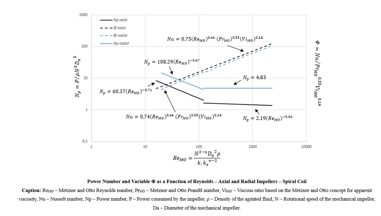
Predictive models for the external convective coefficient yielded adjusted R² values of 0.84 for the axial impeller and 0.83 for the radial one. These models are valid for Metzner–Otto Reynolds numbers between 20 and 385,000, Prandtl numbers from 4 to 6400, and flow behavior indices between 0.45 and 1.0. Comparing heat transfer efficiency, the axial impeller consistently provided external convective coefficients that were approximately 15% higher than those of the radial impeller. This result is attributed to the downward flow pattern generated by the axial impeller, which improves fluid contact with the spiral coil located at the tank bottom.
Regarding power consumption, the radial impeller consistently required more energy in all tests. Therefore, from a mechanical efficiency standpoint, the axial impeller is the preferred choice, independent of the heat transfer surface employed. Power number curves were also modeled mathematically to support design work, with adjusted R² values ranging from 0.60 to 0.98. These models are valid only for non-Newtonian fluids, with Metzner–Otto Reynolds numbers between 20 and 4000 and flow behavior indices between 0.45 and 1.00.
Considering both heat transfer and energy consumption, the axial impeller delivered the best overall performance by achieving higher convective coefficients while consuming less power than the radial impeller, as demonstrated in the attached figure. Finally, the proposed scale-up methods revealed that the relationships between variables for both power and convective coefficients are nonlinear for non-Newtonian fluids. Based on geometric similarity and the three scale-up criteria mentioned earlier, specific models were derived. The predicted errors for these models ranged from 7% to 27%, depending on the condition evaluated.