2024 AIChE Annual Meeting
(584a) Efficient Fuel Atomization Via Spontaneous Wave Swirling
Author
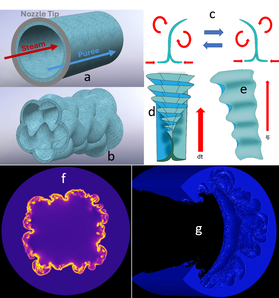
As the combination of fuel and steam exits the atomizer, a kind of “hoop stresses” forms over the body of the annular fuel which acts like a stiff (relative to the gas) cylinder (Figure 1a). Imperfections due to axial disturbances (KHI) and azimuthal disturbances (RTI) along the inner surface of the fluid then result in a creasing effect in response to the imposed stresses (Figure 1b). These creases then extend into the flow of steam. These creases can be thought of as waves also, and these new waves are orthogonal to the main pulsing fuel wave moving through the atomizer. KHI and RTI then begin to develop on both sides of the newly emerged orthogonal waves just as they did with the primary fuel wave. The instabilities gradually begin to pull fuel from the orthogonal waves into small fin like protrusions which reach into the central flow of steam. These protrusions will continue to increase in size as well as exhibit dynamics reflective of the state of the instabilities. As time progresses, the fuel protrusions begin to experience a reduction in tangential velocity as they bend about an axis that is aligned with the central nozzle axis. The velocity will eventually pass through a zero point and begin to accelerate in the opposite direction of the original rotation. This process will then be repeated, resulting in the progressive flapping of the protrusions with each change in rotational direction (Figure 1c). The alternating motion of the fully developed protrusions will also increase in both frequency and amplitude as time progresses (Figure 1d). Further, the height at which the protrusions extend into the steam similarly increases (Figure 1e). There being multiple creases and with this being the inside of the cylinder, the result is a bulk alternating tangential velocity of the edges of the cylinder. Those images represent simplified conceptual views, but Figure 1f depicts a sample snapshot strain rate contour plot from the CFD model showing the developed creases with the SASS motion beginning to develop. Finally, Figure 1g illustrates another sample image of a fuel volume with a quadrant removed for easy liquid shape assessment. It is obvious that waves produce creases, and these creases will develop into tangential motions to be outlined in the full presentation.